 |
|||
|
|
|||
|
Page Title:
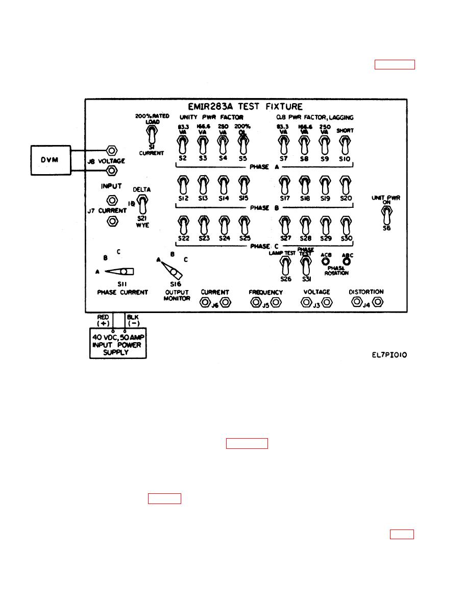
Figure 3-1. Initial Test Setup. |
|
||
| ||||||||||
|
|
 TM 11-6125-259-30
h. After completing voltage measurements, set
assembly (16); be careful of interconnecting wiring.
UNIT PWR switch S6 to down (off) position.
Install A7 assembly with six screws (20), six
Disconnect inverter from test fixture.
lockwashers (21) and six flat washers (22).
i If required at this time, carefully lay A7
component assembly (17) back in place on top of A6
m and n), if required at this time.
Figure 3-1. Initial Test Setup.
3-2. Waveform Check of Component
down.
d. Carefully lay back upper end of A7 component
Assembly A6
assembly (17) 90 degrees over onto work bench.
The instructions in this paragraph are performed
Avoid strain on interconnecting wiring and be sure
only if internal inverter waveforms are required to
metal pins and connections do not touch inverter
be checked on component assembly A6.
case. A6 component assembly is now accessible. See
WARNING
High voltages and currents are present
e. Connect inverter to test fixture as shown in
on disassembled inverter when it is
figure-3-l.
energized. Do not touch any exposed
f. On test fixture, set load switches S2, S12 and
wiring or any metal point within the
S22 to up (83.3 VA) position. Set UNIT PWR switch
inverter: Lethal shock could result.
S6 to ON position and apply 281 vdc input power
to inverter.
g. Connect Oscilloscope AN/USM-281
gains access to A7 component assembly (17).
(oscilloscope) and Counter AN/USM-207 (counter)
b. Loosen A7 component assembly (17) by
to pins 14(+) and 16(-) of component assembly A6.
removing six screws (20), six lockwashers (21) and
The observed waveform shall be as shown in figure
six flat Washers (22).
c. Place inverter on work bench with front side
3-2 and the counter shall indicate a frequency
3-2
|
|
Privacy Statement - Press Release - Copyright Information. - Contact Us |