 |
|||
|
|
|||
|
Page Title:
Chapter 3. DIRECT SUPPORT MAINTENANCE INSTRUCTIONS |
|
||
| ||||||||||
|
|
 TM 11-6125-259-30
CHAPTER 3
DIRECT SUPPORT MAINTENANCE INSTRUCTIONS
Section 1. GENERAL
3-1. Voltage Measurements
CAUTION
When performing d below, make sure
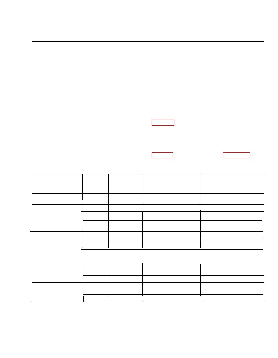
Table 3-1 lists the voltages that can be expected in
component, pine and printed wiring on
the inverter. Perform the instructions in this
A7 component assembly (17) do not touch
paragraph only when necessary to check these
standard voltages.
chassis ground; do not damage in-
terconnecting wiring.
WARNING
d. Carefully lay back upper end of A7 component
High voltages and currents are present
assembly (17) 90 degrees over onto work bench.
on disassembled inverter when it is
Avoid strain on interconnecting wiring. A6 com-
energized. Do not touch any exposed
ponent assembly (16) is now accessible.
wiring or any metal point within the
e. Connect inverter to test fixture as shown in
inverter: Lethal shock could result.
a. Partially disassemble inverter (para 3-0 a and
and S22 to up position (83.3 VA).
b.) gains access to A1, A4 and A5 modules (6 and 34,
f. Set UNIT PWR switch S6 to ON position and
fig. 3-21) and A7 component assembly (17).
apply 28 1 vdc input power to inverter.
b. Loosen A7 component assembly (17) by
removing six screws (20), six lockwashers (21) and
voltmeter), measure the voltages as prescribed in
six flat washers (22).
c. Place inverter on work bench with front side
3-15, 3-17 and 3-18 for location of referenced pins.
down.
Table 9-1 Voltage Measurement
TO
FROM
VOLTS DC
REMARKS
ASSEMBLY
PIN
PIN
A1, EMI
Module
1(+)
l0(-)
27 to 29
A4, Power
Caps and Drive
5(+)
6(-)
37 to 41
A5, Output
13(+)
14(-)
23.0 to 27.0
Filter and
12(+)
13.99 to 14.01
14(-)
Bias Regulator
2(+)
14(-)
4.5 to 4.9
1(+)
4.5 to 5.5
7(-)
5(+)
7(-)
14.5 to 15.5
I
I
I
I
A6, Logic
6(+)
7(-)
4.3 to 4.7
With A output overloaded, see
Note 1.
6(+)
7(-)
9.8 to 10.2
With A output short-circuited,
see Note 2.
TP1(+)
7(-)
3.995 to 4.005
A7, Component
1+)
4(-)
14.5 to 15.5
Assembly, Boost
r
5(+)
4(-)
4.5 to 5.5
Regulator
Note1. This overload condition is obtained by setting switches S1, S2, S3, S4 and S5 (see fig. 3-1) to the up position. Return swit.
ches to down position after taking measurement.
Note 2. This short circuit condition in obtained by setting switch S10 (see fig. 3-1) to SHORT position. Return switch S10 to down
position after taking measurement.
3-1
|
|
Privacy Statement - Press Release - Copyright Information. - Contact Us |
