 |
|||
|
|
|||
|
|
|||
| ||||||||||
|
|
 TM 11-6125-259-30
voltage shall be between 100 and 117.5 vrms.
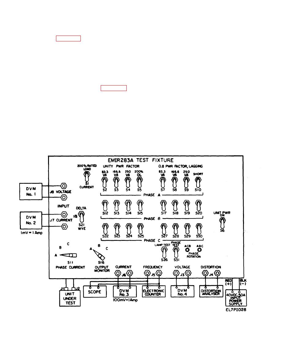
3-5. Test Setup
NOTE
connect fully assembled and closed inverter to test
The test setup and text specified the use
fixture as shown in figure 3-19 (refer to fig. FO 3-20
of four digital voltmeters for simplicity.
for test fixture schematic).
Only one digital voltmeter need be used
3-6. Procedure
and connected, in turn, to any of the four
monitoring terminals on the test fixture.
Perform the following instructions to determine
that the inverter meets operational parameters.
e. Read the percent distortion of output phase as
There are no inverter adjustments and alignments
indicated on Distortion Analyzer TS-723/A. The
nor calibration that should be performed during this
distortion shall be 5 percent maximum.
operational checkout. The initial switch positions of
the test fixture shall be as indicated on figure 3-19
on Electronic Counter AN/USM-207. The
prior to performing the instructions below.
frequency shall be between 393 and 407 Hz.
a. Set the DELTA/1WYE switch S21 to
g. Set OUTPUT MONITOR switch S16 to B and
DELTA position.
C positions respectively and at each position repeat ,
b. Set the UNIT PWR switch S6 to ON position
d through f above for the B and C outputs.
and apply 18 vdc input from the input power supply.
h. Increase the input power supply voltage to 26
c. Set OUTPUT MONITOR switch S16 to A
vdc and 29 vdc respectively, and for each input
position.
voltage repeat c through g above.
d. Read the output phase voltage indicated on
i. Set UNIT PWR switch S6 to OFF position.
Digital Voltmeter AN/USM-281 No. 4. The output
Figure 3-19. Final Test Setup.
3-16
|
|
Privacy Statement - Press Release - Copyright Information. - Contact Us |
