 |
|||
|
|
|||
|
Page Title:
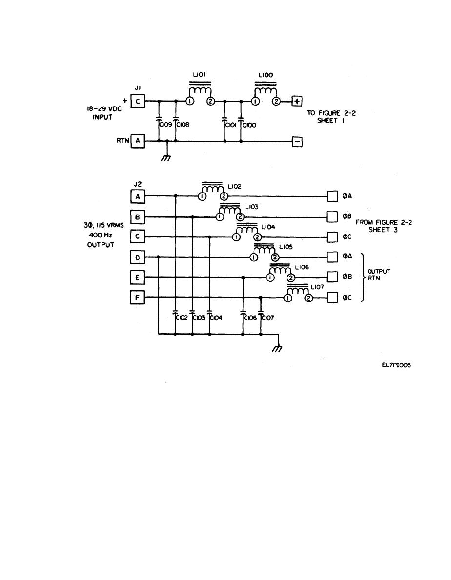
Figure 2-3. Inverter EMI Filter Schematic Diagram. |
|
||
| ||||||||||
|
|
 TM11-6125-259-30
Figure 2-3. Inverter EMI Filter Schematic Diagram.
flow (only discharge current flow) when transistor
When transistor Q700 or Q701 is turned on, trans-
Q700 and Q701 are turned on but the choke center
former T201 or T801 secondary winding 4-3 has
taps are shorted to ground when Q700 and Q701 are
current flow from the +15 volts through Q700 or
turned off.
Q701 to ground. This resets the respective trans-
former. Then when transistor Q700 or Q701 is
The detailed cycling of the boost circuit is: During
turned off, the energy stored earlier causes a back
cycle 1, choke L201 center tap is shorted to ground
EMF through secondarywinding 4-3 that flows
and choke L301 is unshorted and discharging into
through diode CR701 or CR702 to ground. This
capacitors C401A and B. During cycle 2, choke
current flow feeds a voltage into primary winding
L201 and L301 are unshorted and discharging into
1-2 of transformer T201 or T301 and supplies the
capacitors. During cycle 3, choke L301 center tap is
bias voltage which turns on power switch trans-
shorted to ground and choke L201 is unshorted and
istors Q206, Q207, Q208, Q306, Q307 and Q308.
discharging into capacitors. During cycle 4, chokes
Thus, choke L201 and L801 have no charge current
L201 and L301 are unshorted and discharging into
2-3
|
|
Privacy Statement - Press Release - Copyright Information. - Contact Us |
