 |
|||
|
|
|||
|
Page Title:
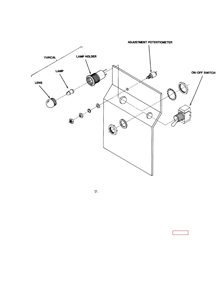
Figure 2-11. Front Panel Disassembly (Sheet 2 of 2). |
|
||
| ||||||||||
|
|
 TM 11-6130-429-40
Figure 2-11
. Front Panel Disassembly (Sheet 2 of 2).
(5) Voltage adjust resistor (R8).
(3) Fault Lampholder (XDS1).
(a) Unscrew lens cap and remove bulb.
(a) tag and unsolder wires from defective resis-
tor.
lampholder.
(b) Remove lock nut, hex nut, lockwasher,
(c) Remove hex nut, lockwasher, and defective
flatwasher, and defective resistor.
lampholder.
(c) Install flatwasher, lockwasher, hex nut,
(d) Install replacement lampholder, lock-
and tighten.
washer, hex nut, and tighten.
(d) Solder wires to replacement resistor (R8).
(e) Solder wires to replacement lampholder.
(f) Install bulb and replace lens cap.
NOTE
(4) ON/OFF switch (S1).
Rear panel disassembly is NOT required
for repair.
switch.
(1) Connector plugs P1, P2.
(b) Remove hex nut, flatwasher, and defective
switch.
flatwashers.
(c) Install new switch, flatwasher, hex nut and
(b) Unsolder and remove capacitors.
tighten.
(d) Solder wires to replacement switch.
|
|
Privacy Statement - Press Release - Copyright Information. - Contact Us |
