 |
|||
|
|
|||
|
Page Title:
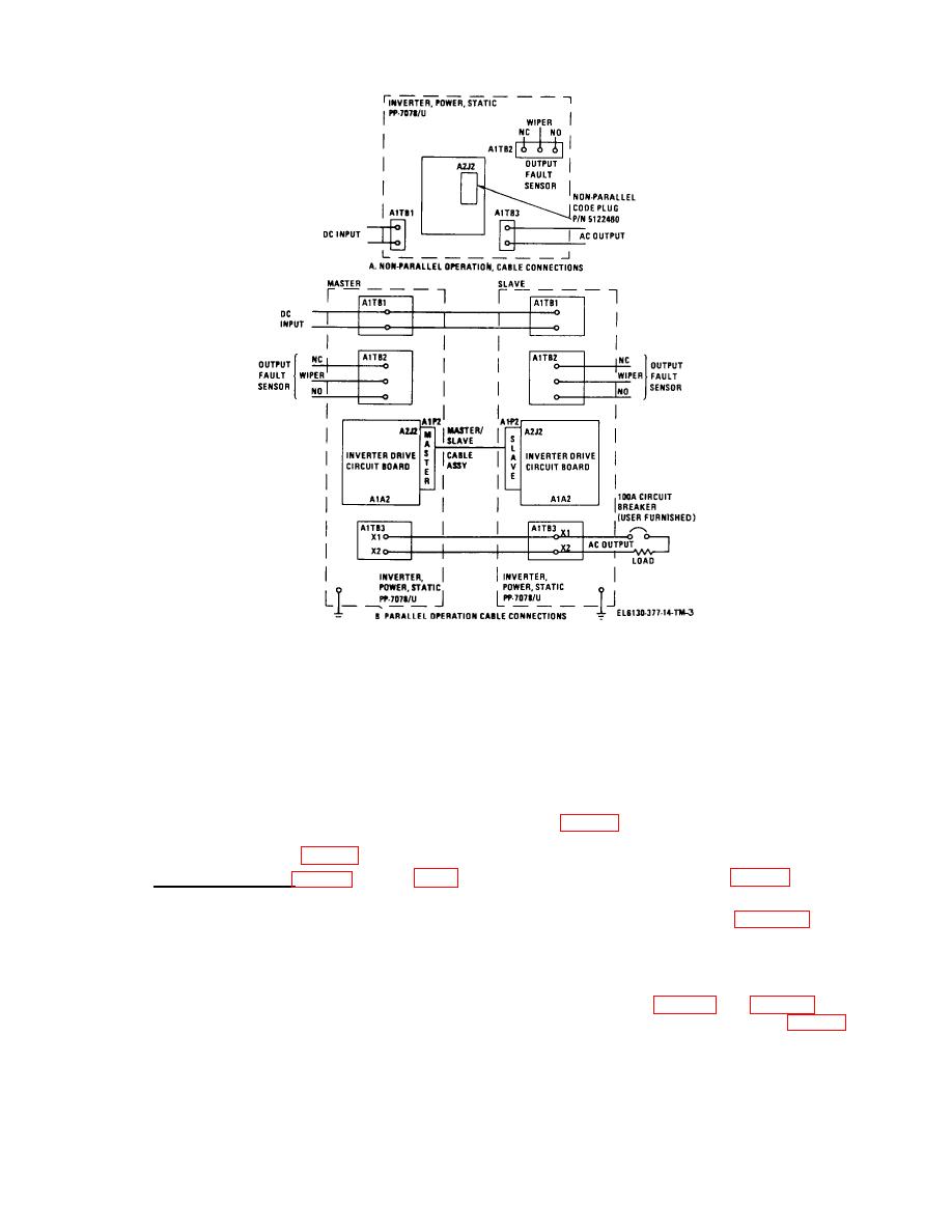
Figure 2-2. Installation wiring diagram for single and dual operation. |
|
||
| ||||||||||
|
|
 TM 11-6130-377-14
Figure 2-2. Installation wiring diagram for single and dual operation.
(a) Connect the bond (ground) strap from
NOTE
the GROUND terminal, located on the lower edge at the
The inverter which receives the
rear of the inverter, to a suitable earth or ship's-hull
Master/Slave Cable plug placarded
ground.
MASTER will control the inverter to
(b) Pass the input and output cables
which the SLAVE plug of the cable is
through the packing glands located in the rear panel of
installed.
the inverter and route them to their respective terminal
(c) Install
the
master/slave
cable
boards.
assembly (fig. 1-1) between the inverters and connect the
(c) Connect the dc input cables to A1TB1
MASTER plug into receptacle A1A2J2 of one inverter
and the ac output cables to A1TB3 (fig. 2-1).
drive board and the SLAVE plug into the other inverter
drive board receptacle A1A2J2 (B, fig. 2-2).
(2) Parallel connections (fig. 2-1, and B, fig. 2-
2). In this arrangement the user must provide the input
(d) Complete the remaining cabling for
and output cables, the inter-unit cables, and a 120 volt,
DC IN and AC OUT as shown in B, figure 2-2.
100 ampere single pole circuit breaker. The circuit
(e) Clost front panels of both inverters and
breaker is placed between the ac output terminals of the
secure the captive screws.
slave inverter and the load. The wire size for the dc
c. A remotely located indicator device can be
cables is AWG#3/0 and for the ac cables is AWG#1.
connected to A1TB2 (fig. 2-1 and fig. 2-2). Terminal
(a) Open the front panel of each inverter
board A1TB2 is connected to relay A1K4 (fig. 5-2) whose
to gain access to the inverter drive circuit board.
contacts are capable of operating at 2 amperes
(b) Remove the Code Plug (P-2) from the
inverter drive circuit board of the two inverters being used
in parallel.
2-3
|
|
Privacy Statement - Press Release - Copyright Information. - Contact Us |
